
HOMEBREW AERIALS
I am not a mechanical engineer so I take a DIY-style approach to aerial construction.
Most components that I use are from electronics suppliers, DIY shops and local hardware outlets.
Most of my cables and coaxial connectors come from Moonraker.
1. 100' (30m) long wire at about 5' above ground (80m and 40m)
2. Indoor inverted vee dipole in the attic (20m to 10m)
3. Three element beam (2m band)
4. Four element beam (2m band)
5. Seven element beam (70cm band)
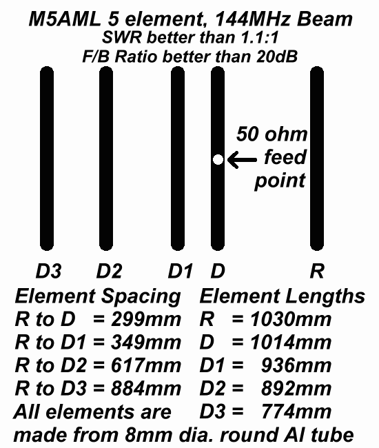
6. Short five element beam (2m band)
7. Gutter mounted wire dipole (20m to 15m mainly)
8. Indoor nested inverted vee dipole (40m, 20m, 17m, 15m and 10m)
9. Indoor dropped-end dipole (20m to 10m)
10. Indoor bent (V) dipole (40m to 6m at a push)
1. The longwire ran up one side of my garden (north east to south west) next to a wooden fence. Its height above ground was on average 5' (under 2m). At the house end of the wire there was a metal tube which I knocked into the ground to form some kind of earth. This was where I connected my ATU and ran co-ax through the conservatory window to my radio. I have successfully contacted stations in Wales, England, Scotland and Holland with this aerial on the 80m and 40m bands. This aerial was a real compromise but was invisible to neighbours! This aerial is really invisible now because I have taken it down so it isn't damaged during hedge cutting. Now dismantled.
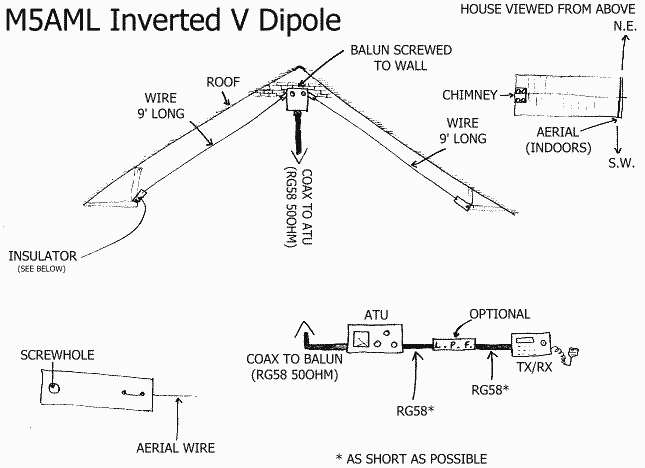
2. My inverted vee was my first amateur antenna and was the most used. It is situated in my attic and by using my ATU I can make contacts on any band between 40m and 10m. Performance is best on 17m and 15m and it really becomes poor at the lower end of 20m and on bands above 12m. Good contacts have been made at these extremes into Europe and during sporadic E openings on 10m. DX has been worked with just 5 or 10W PEP on 15m when conditions have been favourable. Now dismantled.
3. For some 2m FM work I made a 3 element 2m band beam. I designed it using MMANA software and it has a theoretical front to back ratio of over 18dB. It is a real Heath Robinson affair at the moment - I used the ribs from an old golf umbrella, which were 2mm diameter for the elements and screwed these onto a piece of 1/2" timber from B&Q. I later replaced the director and reflector ribs with 2mm fence wire which I fixed onto the boom using hot-melt glue. The whole thing is fed using not-so-ideal RG58 coax with a BNC which is then adapted to an SMA connection for use with my VX5-R. This highly lossy method of feeding still gives me strong West Midlands stations at S9+ and also GB3DX (S4), GB3HH (S2), GB3VT (S3), GB3IN (S9) and of course GB3CF (S9).
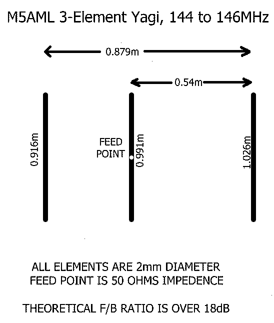
The directivity of this aerial is quite impressive. At the moment I use it in my shack, balanced on top of a wardrobe. I have made contacts with a maximum of 5W PEP into North Nottinghamshire, West Midlands, Shropshire and under lift conditions Essex and I have even opened a French repeater! One summer I joined some clothes props together to form a 19' mast and put my Yagi on top. I could actually hear quite a few stations from the north including Barnsley and NW Manchester. Sadly this "mast" was too difficult to put up due to it tangling up in a couple of trees and a washing line, so now I am experimenting with an 8m long telescopic roach pole.
4. I wanted to increase signal strength on 2m so I designed (using MMANA) a four element beam antenna with a greater F/B ratio than the 3-element aerial shown above. Initial tests showed that the directivity of the aerial was better than the 3-element but overall received signal strength was only marginally better than before.
This aerial was much larger than the 3-element which made it very
difficult to handle especially indoors. The small improvement in
performance over the 3-element beam didn't justify keeping the
4-element, so within hours of constructing the 4-element aerial, I
dismantled it and then constructed a 70cm aerial (details below).
This 4-element aerial was constructed using 1/2" timber as the boom and
the elements were made out of 2mm diameter steel fence wire. I didn't
have any more umbrella ribs but I had acquired some of this wire which
was much easier to cut than the umbrella. The elements were attached to
the timber using hot-melt glue.
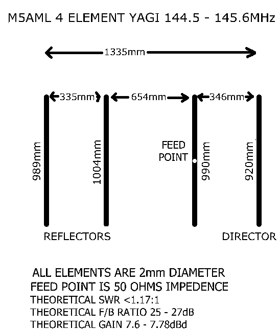
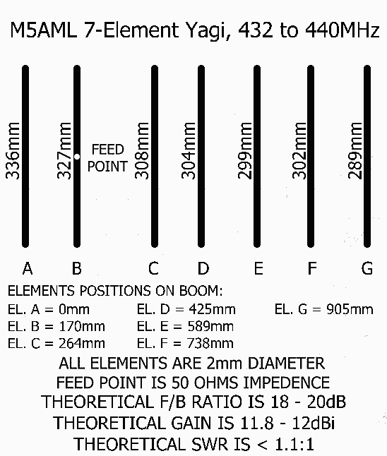
I have tried this aerial mounted on a
camera tripod indoors mainly on SSB in the RSGB UK Activity Contests
and have worked as far as northern France without any difficulty using
5W.
Since moving to a new QTH this aerial is now mounted in the loft on a Daiwa rotator fed with Moonraker's Formula
Zero coax. Within the first twelve months of trying this new set-up
I have worked into the Isle of Man, E. Wales, N. England, S.W. England and Scotland - all on SSB.
7. A new QTH meant new antenna requirements. Not wanting to bother my neighbours the first was a gutter mounted wire dipole which was 23' 4" (7.112m) long and only 8' (2.4384m) above ground. The thin wire, which was taken from some old telephone cable, was clipped to the conservatory and garage gutters using plastic washing-line pegs and fed using RG58 coax via a balun. Using an ATU this aerial was most effective on the 20m, 17m and 15m bands. SSB contacts were made with stations throughout Europe and even the Carribean running just 5W from the transceiver. Now dismantled
8. Although I had some success with the gutter mounted dipole it was not a great performer but considering its height above ground and virtual invisibility it certainly was not a terrible aerial. An inverted vee dipole was next made from 16SWG wire and fed using RG58 coax via a balun. This antenna was situated in my attic and was made from approximately 30' (9.144m) of wire - 15' in each half. It was mounted diagonally across the attic from one corner to the opposite corner so I could get more wire in. In this state it was good on 20m and 40m at a push, both using an ATU.
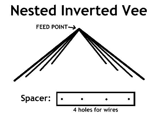
Later I installed additional shorter, thinner parallel wires which were connected to the feed point and tuned for different bands. Plastic electrical conduit lid was cut into short lengths and holes drilled in each length to accommodate the wires. These spacers were hung from the main 16SWG wire and the additional wires were threaded through the remaining holes. The wires were tuned to best resonance by folding them back on themselves. This effectively shortens the wire without cutting. When doing this the wires interact with each other so it can be quite tricky to do but it is worth the effort.
I managed to still use the 16SWG wire for 40m and 20m and I had a 17m wire, and 15m wire and a 10m wire. Sometimes the ATU was needed mainly for 40m, 20m and the extremeties of 10m, otherwise this antenna was resonant. Now dismantled.
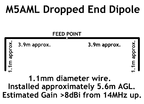
9. Due to proposed regulations in the UK limiting public exposure to RF fields and the fact that I had reverted my nested inverted vee to a single inverted vee which did not perform well I decided to look at a different indoor aerial system. The challenge was to fit a good amount of wire in the attic without getting too close to my neighbours' property. After lots of measuring, muttering and noodling on MMANA I came up with what I call the Dropped End Dipole. This is not a new concept but it is not well documented. It is basically a horizontal dipole where the far ends of the wires drop vertically. I used 1.1mm diameter stranded PVC coated wire fed using RG58 via a balun. Each horizontal section of wire is approximately 3.9m in length and each vertical drop section is around 1.1m long. The wire is strung through small screw-in eyes from Homebase.
Using an ATU this antenna can easily tune up on 40m to 10m and has so far been used with 5W SSB to make contact with Sicily and Finland on 17m and Ireland on 20m. SSB stations from Kuwait and USA have been heard on 20m, 17m and 15m.
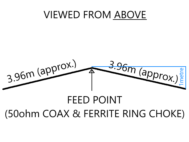
10. Due to proposed regulations in the UK limiting public exposure to RF fields and the fact that the dropped end dipole performed poorly I decided to try a bent dipole as an alternative way to fit a good amount of wire in the attic without getting too close to my neighbours' property. After a lot of noodling and crawling about in the loft I came up with what I call the Bent Dipole or "V" Dipole. This is not an Inverted-V Dipole! It is a horizontal dipole where each leg is bent in slightly towards the opposing leg (see diagram below andvideo HERE). I used 1.1mm diameter stranded PVC coated wire fed using RG58 via a balun. Each horizontal section of wire is approximately 3.96m in length. The wire is strung through small screw-in eyes from Homebase.
Using an ATU this antenna can easily tune up on 40m to 10m and is also good for some 6m work. It seems to perform better than the dropped end dipole.
